Building Cross Connects with Splitters
This guide walks through building a cross-connect through a fiber splitter in Vision — connecting an OLT PON port, through the splitter, out to your patch panel ports.
The example below uses a 1x4 splitter on Card 2, PON 1. The same steps work for any splitter size. The only thing that changes is how many circuits you build: always splitter size + 1 (one input, plus one output per leg). A 1x4 needs five circuits; a 1x8 needs nine.
You don't have to build a splitter out completely in one sitting. Building incrementally is fine — just always finish at least one full input-to-output connection before you stop.
Table of Contents
- Overview
- Before You Begin
- Step 1 - Find an Available Splitter
- Step 2 - Purchase Order a Splitter
- Step 3 - Open the Hardware You'll Connect
- Step 4 - Label the Splitter
- Step 5 - Find Available Circuit Segments
- Step 6 - Purchase Order Circuit Segments
- Step 7 - Build the Input Circuit (OLT to Splitter)
- Step 8 - Build the Four Output Circuits (Splitter to Patch Panel)
- Step 9 - Verify the Cross Connect
- Updating the Imported drop
Overview
The diagram below shows the overall fiber path from the OLT, through the splitter and patch panel, and out toward the final service locations.
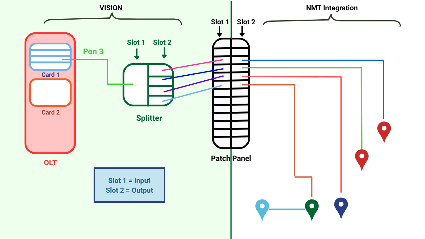
On the left side of the diagram, the Vision-managed portion includes the OLT PON port, the splitter, and the patch panel inputs. In this example, PON 3 from the OLT connects to a splitter, such as a 1x4 splitter. The splitter outputs are then connected to the desired input ports on the patch panel.
The right side of the diagram represents the NMT integration side. Once the connection reaches the patch panel outputs, NMT handles the remaining path from the patch panel out to the associated homes or service locations.
In this setup, Slot 1 represents the patch panel input side and Slot 2 represents the patch panel output side. The selected Slot 1 inputs should match the Slot 2 outputs that are already connected to the intended field locations. These output connections are typically already determined by the physical patch panel wiring, service area design, or existing fiber assignments.
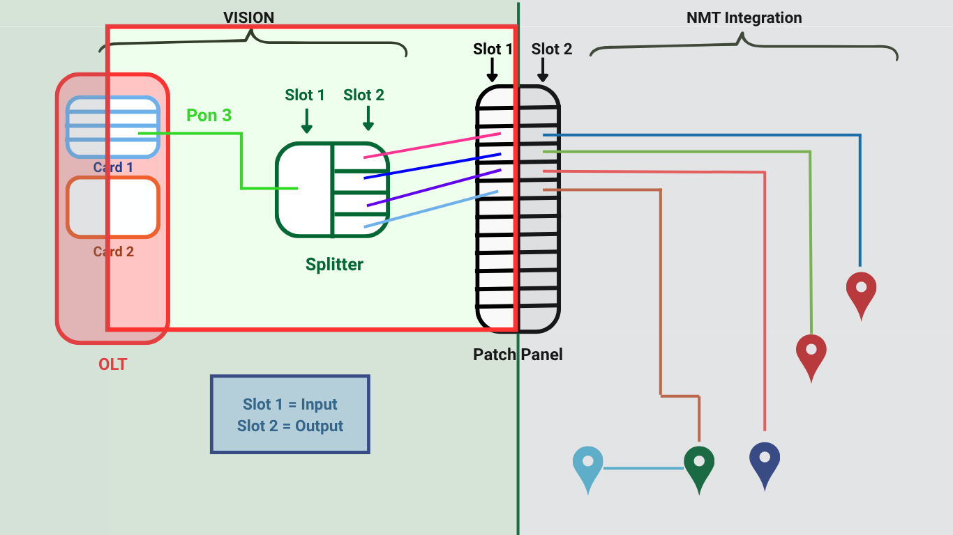
The second diagram highlights the specific portion covered by this documentation. The red box shows the Vision-managed cross-connect work: connecting the OLT PON port to the splitter, then connecting the splitter outputs to the correct Slot 1 inputs on the patch panel. This ensures the Vision side of the connection lines up with the NMT-managed outputs that continue to the homes.
Before You Begin
- Your patch panel must already exist in the system. It typically comes in through your network management integration once the first drop at the location has been imported.
- You'll be jumping between several pieces of hardware, so a quick tip: hold Ctrl and click a hardware ID in a list to open it in a new browser tab. You'll lean on this throughout.
- The hardware IDs you'll need are the OLT/Card, the patch panel, and the splitter. It's worth keeping these tabs open or having the IDs ready on your clipboard.
Step 1 - Find an Available Splitter
First, check whether you already have an open splitter to use.
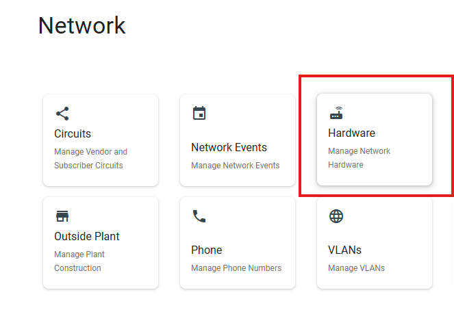
- Open Network > Hardware.
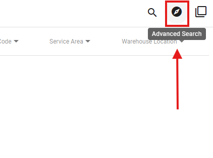
- Click the Advanced Search option

-
- Set your filters: Product Type = Fiber Splitter Manufacturer = your placeholder manufacturer and Size = the splitter you need (1x2, 1x4, 1x8, etc.).
-
- Click

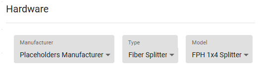
If an unused splitter of the right size appears (You can check if it is unused by opening the hardware and checking if there are circuits tied or not), move it to the warehouse you're working in, then skip to Step 3:
- Open the splitter hardware by clicking on it.
- Click the

- Type in the relevant warehouse to move the splitter to.

- Skip to Step 3.
If none are available, continue to Step 2.
Step 2 - Purchase Order a Splitter (if needed)
Skip this step if you already have a splitter ready in your CO.
- Open the hamburger menu > Inventory > Purchase Orders.
-
- Click the plus (+) to add a new purchase order. Choose "General Purchase Order".
-
- Set the manufacturer to your placeholder manufacturer, with the default address and term, then add a line item for Fiber Splitter at the size you need.
- If that size isn't in the product list, click Add New Product, set the manufacturer to your placeholder manufacturer, with the default address and term, and add the model you need.
- For simplicity, ship the order directly to the warehouse where you'll use it and click SUBMIT.
- To generate the hardware, click Edit > Line Items > Received, then Complete Purchase Order.

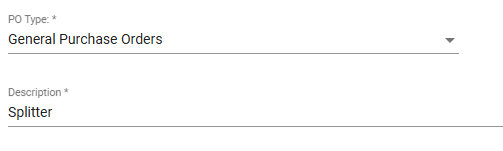
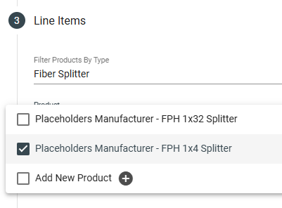
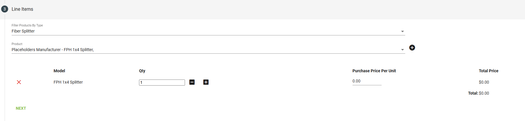
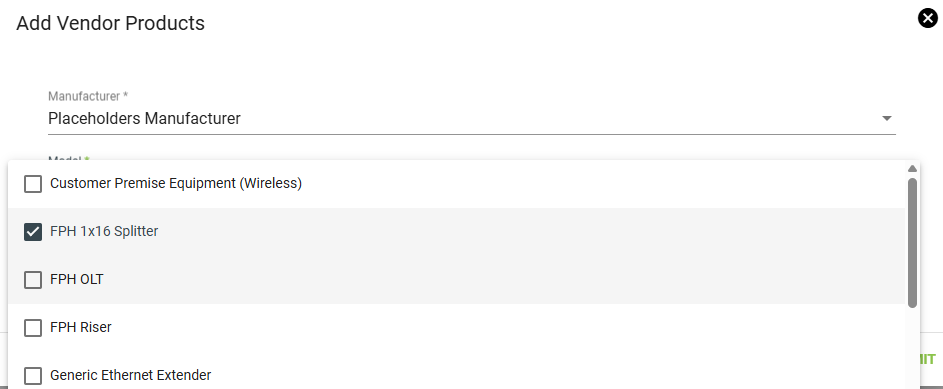

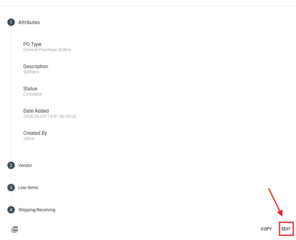
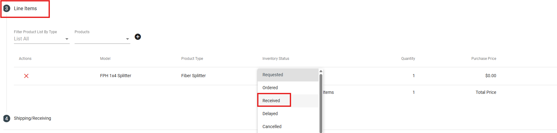
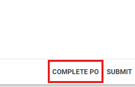
Completing the purchase order creates the splitter hardware in your warehouse.
Step 3 - Open the Hardware You'll Connect
Navigate to your warehouse (Inventory > Warehouse) and open the three pieces of hardware involved in the cross connect:
- The OLT card
- The patch panel
- The splitter you're using
Ctrl + click each hardware ID to open it in its own tab.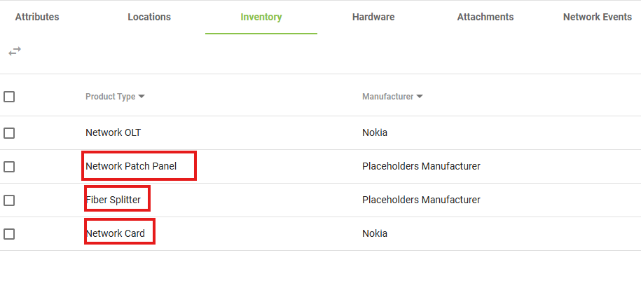
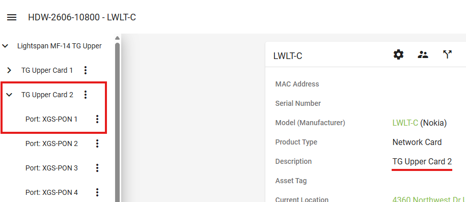
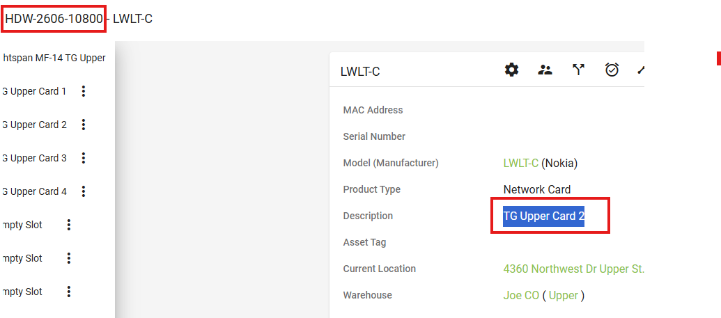
One note on the OLT: if your OLT has cards built into it, click into the individual card to get that card's hardware ID. In this example we're working on PON 1 of Card 2, so open Card 2 — that's the network card your PON ports live on.
Step 4 - Label the Splitter
Good labeling means anyone can look at this splitter later and immediately see what it connects to — the OLT port it comes from and the patch panel ports it feeds.
- On the splitter hardware, click Edit Hardware > Hardware Components.
-
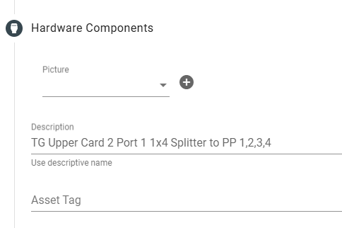
- Edit the component description using a naming convention that captures both the source (OLT card and port) and the destination patch panel ports. Keep it simple and consistent so it reads cleanly in a list view.
-
-
- In this example, the description names the card (TG Upper Card 2), the physical port the connection comes from, the splitter name, and the patch panel ports it goes to (1, 2, 3, 4).
- Click Update.
Now anyone reviewing this splitter can see exactly which patch panel ports it's meant to reach.
Step 5 - Find Available Circuit Segments
You'll build one circuit per connection. For a 1x4, that's five: one input circuit (OLT to splitter) and four output circuits (splitter to patch panel).
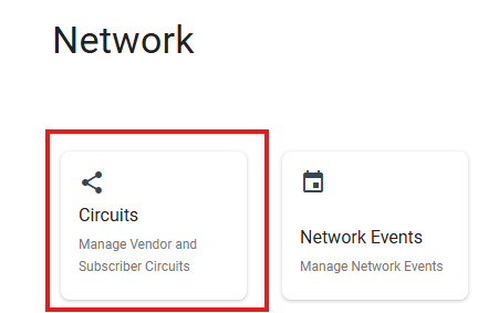
- Open the hamburger menu > Network > Circuits.
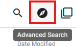
- Click Advanced Search

-
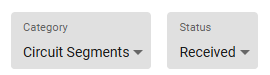
- In Advanced Search, set Category = Circuit Segments and Status = Received (these are your unused circuits).
-
-
- Click

- From the results, filter by Circuit Type = Fiber Circuit. (This filter isn't part of Advanced Search — you apply it to the results after you click Search by clicking on the column title.)

If you have enough unused fiber circuits, Ctrl + click each one to open its receiving screen in its own tab — five for a 1x4 — then continue to Step 7. If you don't have enough, build them with a purchase order in Step 6 first.
Step 6 - Purchase Order Circuit Segments (if needed)
Circuits use a different purchase order type than hardware.
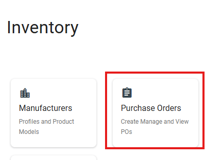
- Open the hamburger menu > Inventory > Purchase Orders and add a new one, choosing the Circuit Purchase Order type.
-
-

-
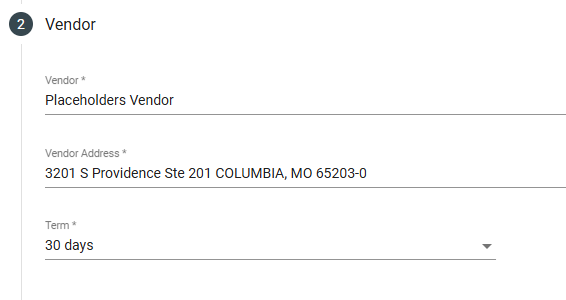
- Set the vendor to your placeholder vendor.
-
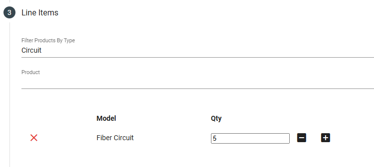
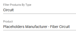
- Add a Fiber Circuit line item. If it isn't in the product list, use Add New Product.
-
- Add plenty at once so you don't have to repeat this every time.
-
-
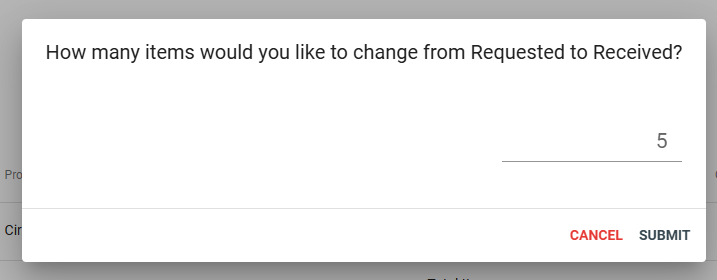
- Ship them to your placeholder warehouse or a dedicated circuit warehouse, so they don't clutter your other central offices and inventory. Once the full quantity arrives, click Edit > Line Items > Received, then Complete Purchase Order.
-
-
Once that's done, repeat Step 5 (or refresh that tab) to open the relevant circuits.
A Quick Note On Splitter Slots
Before you start receiving circuits, it helps to understand how Vision models a splitter's ports.
The ports are grouped into two slots.
- Slot 1 holds the input ports
- Slot 2 holds the output ports
This is always the case. So your single input circuit lands on Slot 1, and every output circuit lands on Slot 2. Keep that rule in mind through the next two steps.
Step 7 - Build the Input Circuit (OLT to Splitter)
With your receiving tabs open from Step 5, start with the input circuit, which connects the OLT to the splitter's input:
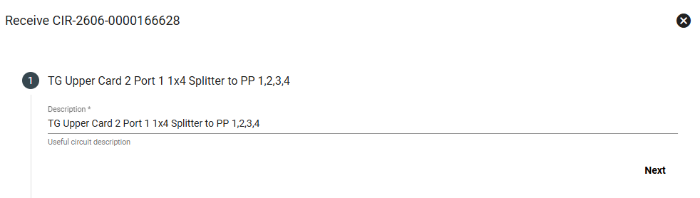
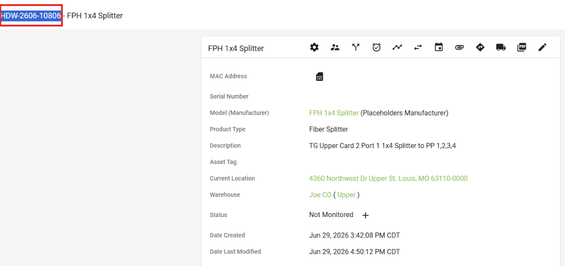
- Description: This one is slightly different from the others. Copy the splitter's description and paste it in exactly, so anyone can trace where this circuit ultimately leads.
-
-
- Click Next.
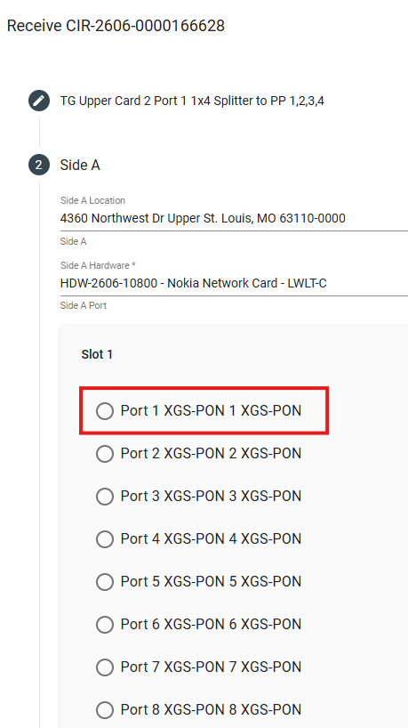
- Side A hardware = the OLT card. Paste the card's hardware ID, select it, then choose the port — Card 2, Port 1 in this example. Click Next.
-
-
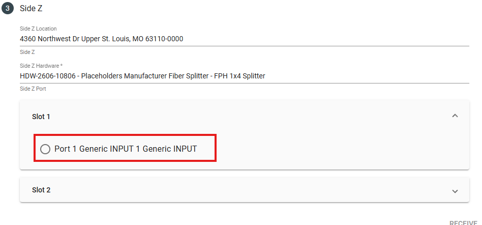
- Side Z hardware = the splitter input. Paste the splitter's hardware ID, select it, then choose Slot 1 (the input slot), Input Port 1.
-
-
- Click Receive.

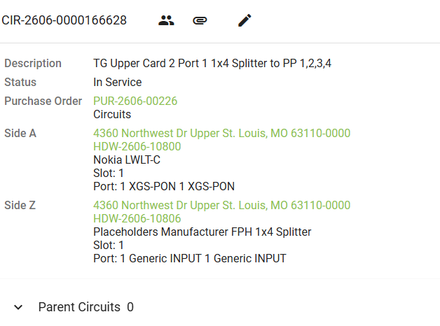
The input circuit is done. You can close the tabs you're finished with (the OLT tab, this circuit's tab, and the circuit list tab) to keep things clean and free up memory.
Step 8 - Build the Four Output Circuits (Splitter to Patch Panel)
Now build the four output circuits across your four remaining tabs. In this example, each output port on the splitter maps to one input port on the patch panel, in order — output 1 to input 1, output 2 to input 2, and so on.
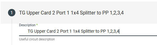
First, set each description. Paste the splitter description and add which patch panel port that circuit goes to — In this example, Port 1, Port 2, Port 3, Port 4. (Ctrl + Tab moves you to the next tab.)
Then complete each one the same way:
- Click Next.
- Side A hardware = the splitter. Paste the splitter's hardware ID, select it, and choose Slot 2 (the output slot), Output Port — 1, 2, 3, or 4 to match the tab.
-
- Click Next.
- Side Z hardware = the patch panel. Paste the patch panel's hardware ID, select it, and choose Slot 1, Input Port. And select the input port you are intending to model the circuit to.
- Click Receive, then close the tab (Ctrl + W).
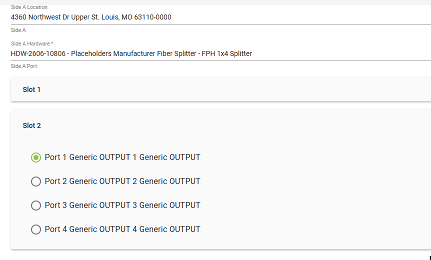
Repeat for all four output ports. When the last one is finished, close the patch panel tab.
Step 9 - Verify the Cross Connect
Refresh the splitter tab. Open the Circuit menu next to its hardware ID and expand it — you should see the splitter fully cross-connected, with the input and all four outputs in place.
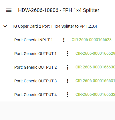
As noted up top, it's best practice to complete a full splitter at a time when you can, but stopping after any complete input-to-output leg is fine.
Updating the Imported Drop
As mentioned at the start, your patch panel came in from an imported drop. Right now that drop won't be valid, because the cross-connects didn't exist yet when it was imported. There are two ways to fix this.
Option 1 — Re-import (best for workflows that haven't been installed yet)
If possible, open the installation workflow and find the task with your Drop Construction Map. Open the map and select re-import. This updates the circuit, and it will then follow your new cross-connect circuits back to the source.
Option 2 — "Walking the circuit back" (quickest; best for already-installed workflows)
- Navigate to the subscriber and open the Parent Circuit (this is typically attached to your fiber speed line item).
- Click Edit. In the edit interface, the Side A Vendor Circuit field reads "Imported Circuit." This means the circuit's Side A currently terminates at the last imported piece of hardware — typically the patch panel.
- Take the CIR ID of the circuit that connects to the correct patch panel port (from Step 8) and paste it into that box. Wait for the dropdown to appear, then select the relevant circuit. Click Update details. The circuit now reads as if Side A terminates at the splitter.
- Repeat the previous step with the CIR ID you created in Step 7 (the OLT-to-splitter input circuit). You're all set — the drop now traces all the way back through your cross-connects.