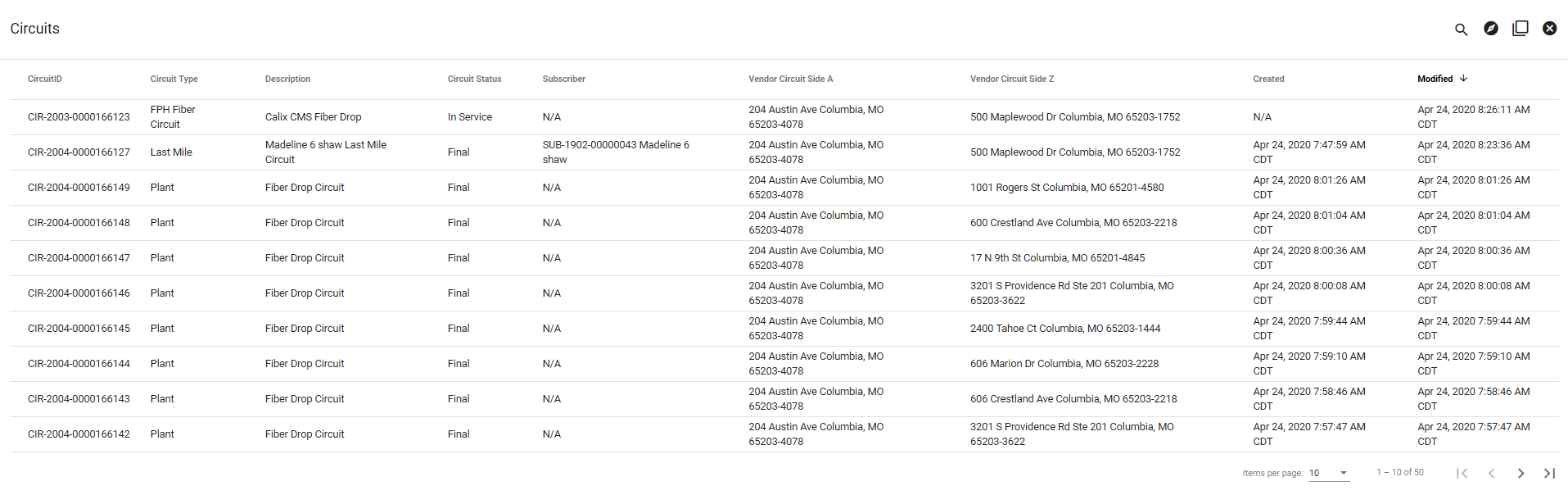
Circuits
The Circuits page will display all Fiber Circuits in your network. By default, Circuits will be displayed starting with the most recently modified. Use the search tools in the upper right to navigate through your Circuits.
You may click on a Circuit here to view more information, but you will most often end up viewing a Circuit from another page, such as a Subscriber's package view or from the Network Monitoring page.
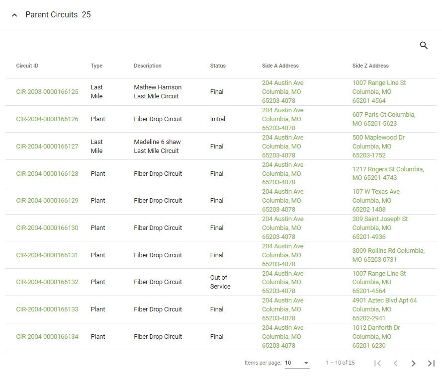
Parent Circuit
A Parent Circuit is the entire path of service from your network to an endpoint or Subscriber. For instance, a fiber connection Parent Circuit would be made up of hardware and fiber drop cables. The various paths within a Parent Circuit are called Vendor Circuits. For better understanding, view the graphic below.
View Parent Circuit
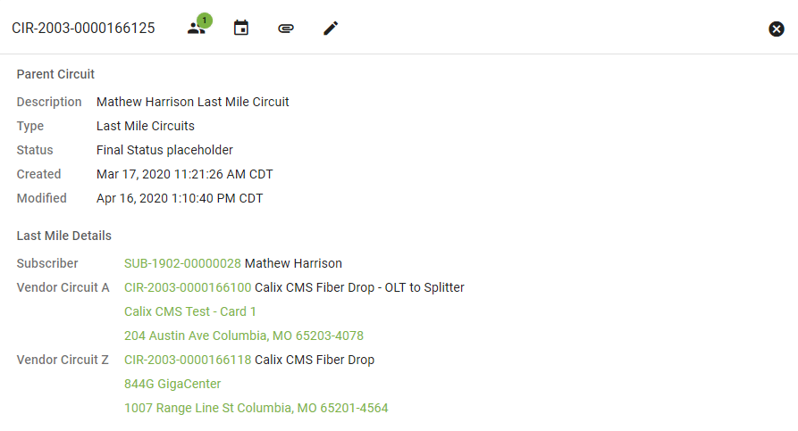
The Parent Circuit view is separated into attributes, segments, and the map view of the Circuit. At the top of the page there are icons to do the following:


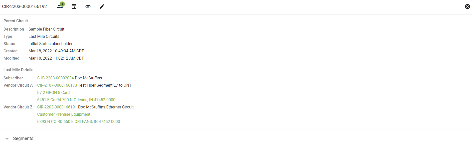
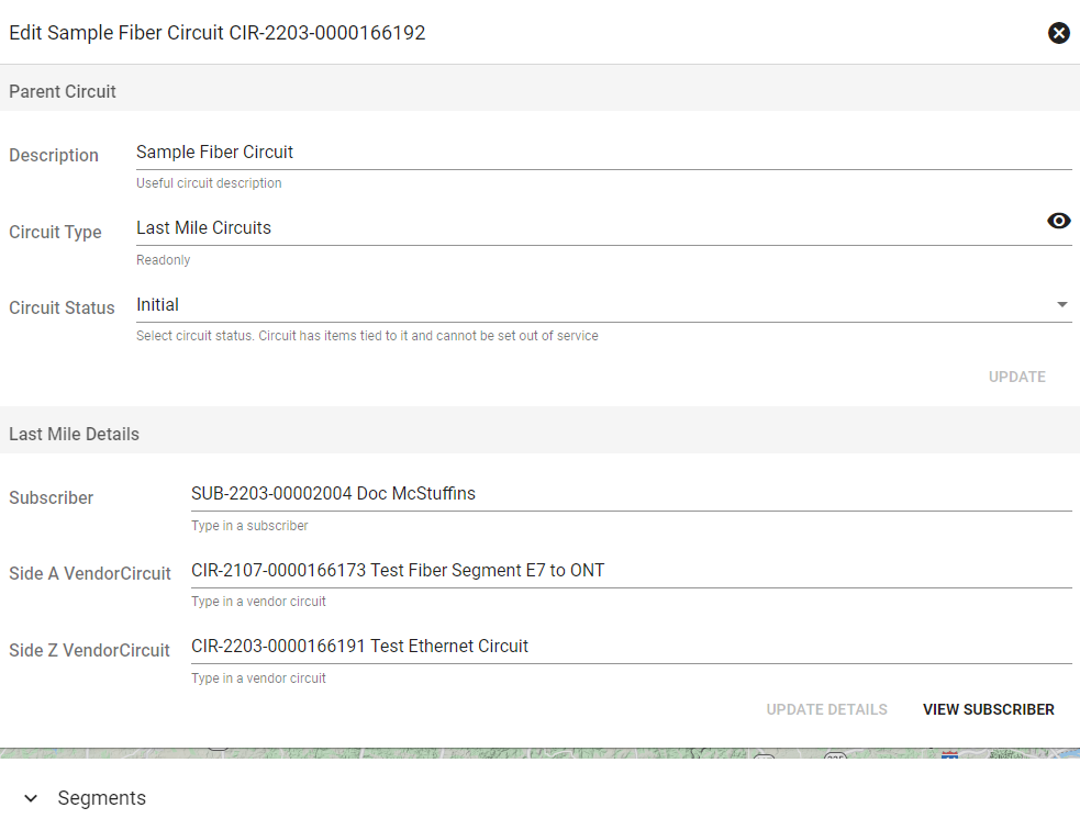
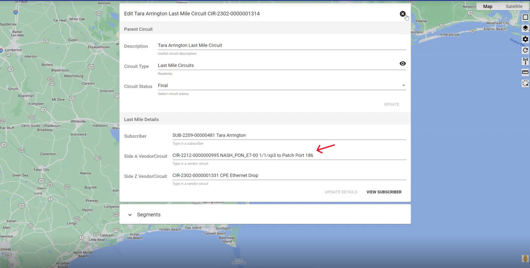
This is a Last Mile Circuit for a Subscriber. Below Last Mile Details we have links to view the associated Subscriber followed by Vendor Circuit A and Z.
Vendor Circuit A refers to the starting Circuit within this subscriber's Parent Circuit. Click on the Circuit name to view more information. Below the Circuit name we'll see the Hardware that this Circuit is tied to and its Location.
Vendor Circuit Z is the endpoint of this Parent Circuit, in this case the Subscriber's location.
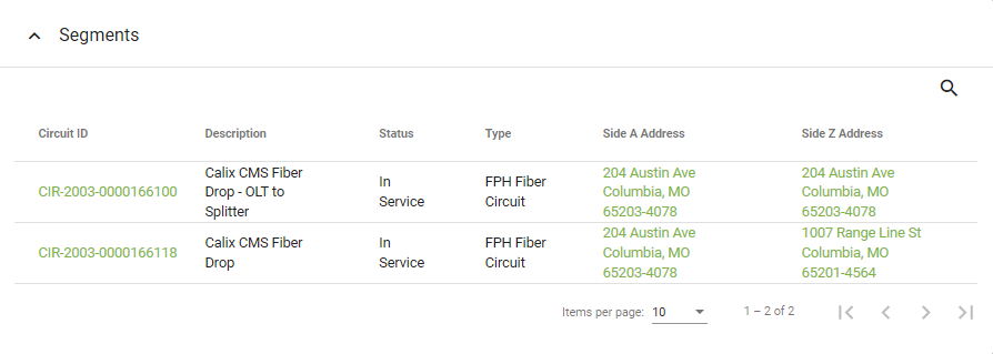
Under Segments you can view all of the Vendor Circuits that make up the Parent. This simple Parent Circuit is only made up of two Vendor Circuits. Click the Circuit ID for more information. You may also click on the Side A Address (the starting point of the circuit) or the Side Z Address (the end of the circuit).
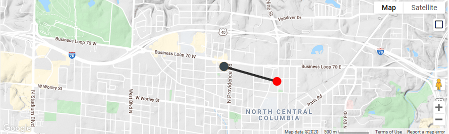
The map view of the Circuit will show the path with nodes designating different pieces of Hardware.
Edit Parent Circuit
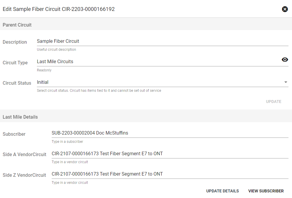
Making changes to an existing ethernet circuit can be necessary in some situations. For example, it can be necessary to update Vision to match a change in the customer's configuration, like if they want to change routers.
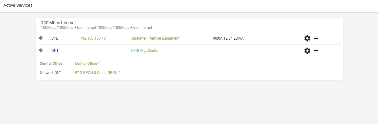
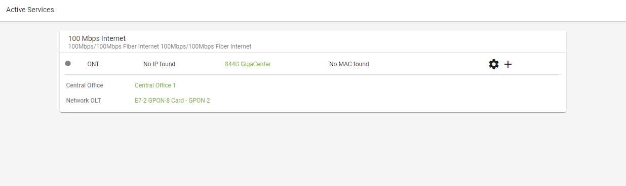
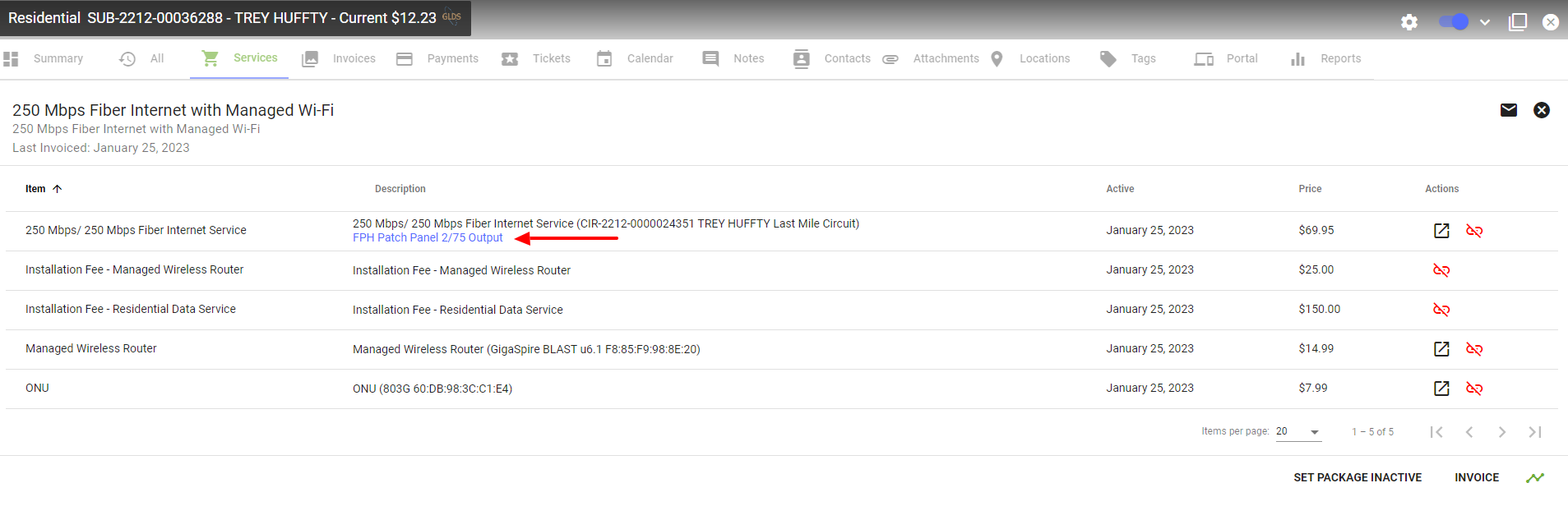
The active services card will display devices that are connected to the subscriber account.
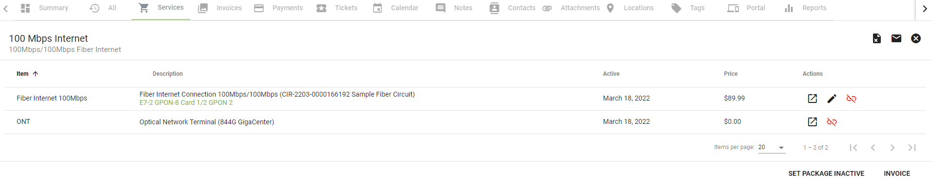
From the services tab, click on the applicable package, then select the 
View the current circuit associated with that subscriber and the devices. Click on the 
Replace the Side Z circuit with the circuit description from the first ONT port.
Click UPDATE DETAILS to save the new circuit information.
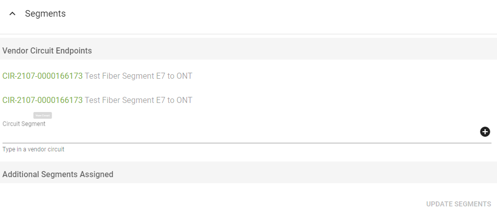
From the Segments drop-down, click the 
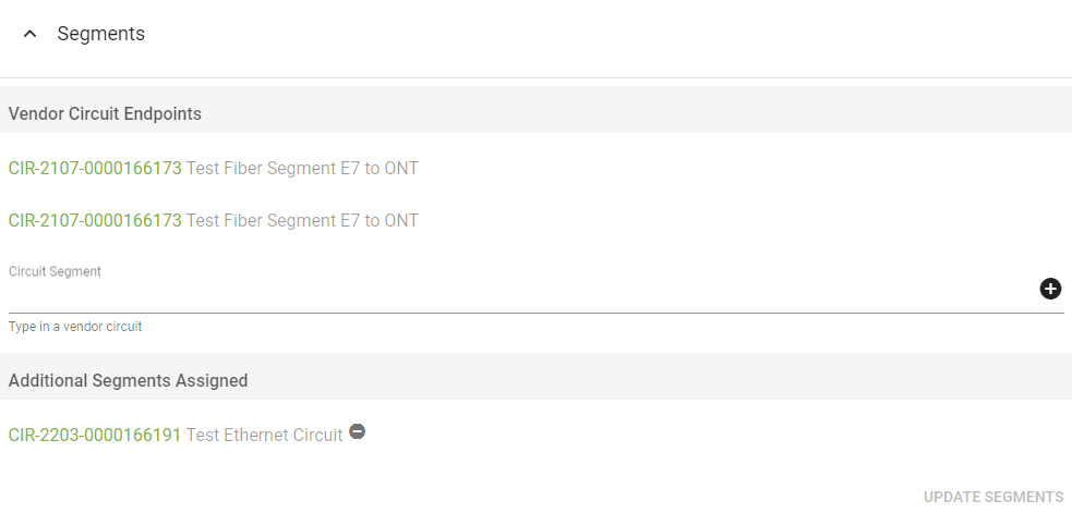
Select UPDATE SEGMENTS to save the changes.
The active services card will no longer display the previous customer equipment.
Add Circuit
Click the 
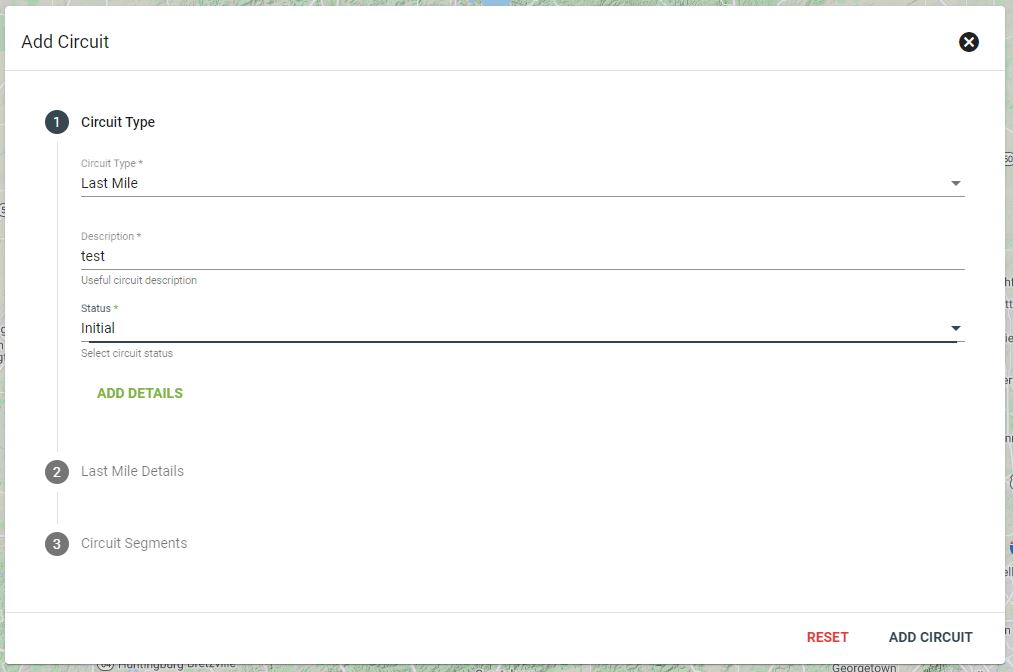
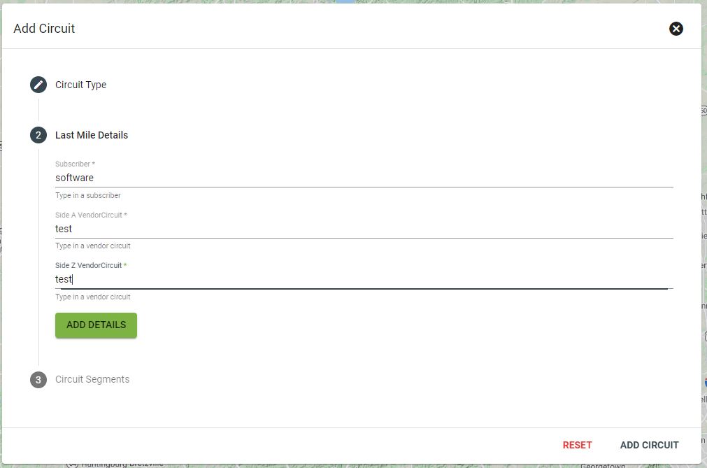
Input the last mile details, including the subscriber, side A vendor circuit and side Z vendor curcuit. Click ADD DETAILS when complete.
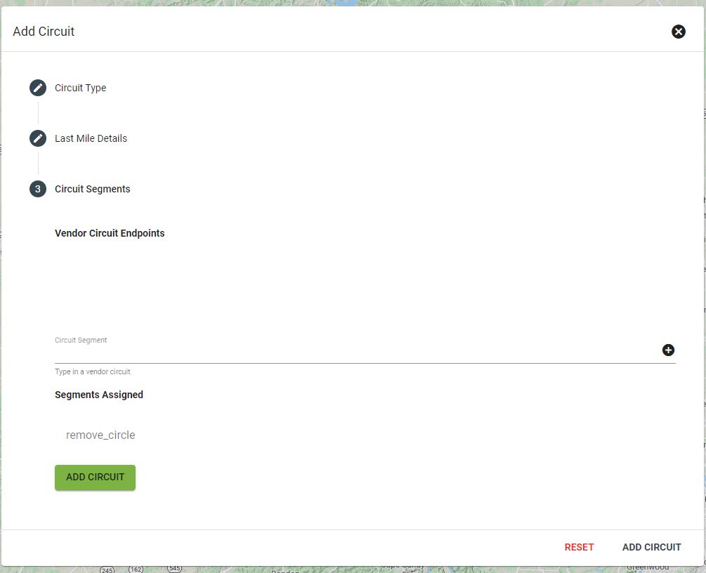
Enter any vendor circuit endpoints, then click ADD CIRCUIT to complete the process.
Extending Circuit/Cross Connect
As your company grows and adding new subscribers extending your circuits is necessary to make turnups easier for your technicians. Cross connecting circuits allows for easier identification of which users may be effected by an outage. Having all your hardware in order makes for a streamlined process when handling technical support issuses.
Creating a relationship between the fiber patch panel to the PON port is import to help finish a ciruit to a subscriber.
To create a connection, Click to open service items ![]() from the services tab
from the services tab ![]() to find the parent circuit and patch panel.
to find the parent circuit and patch panel.
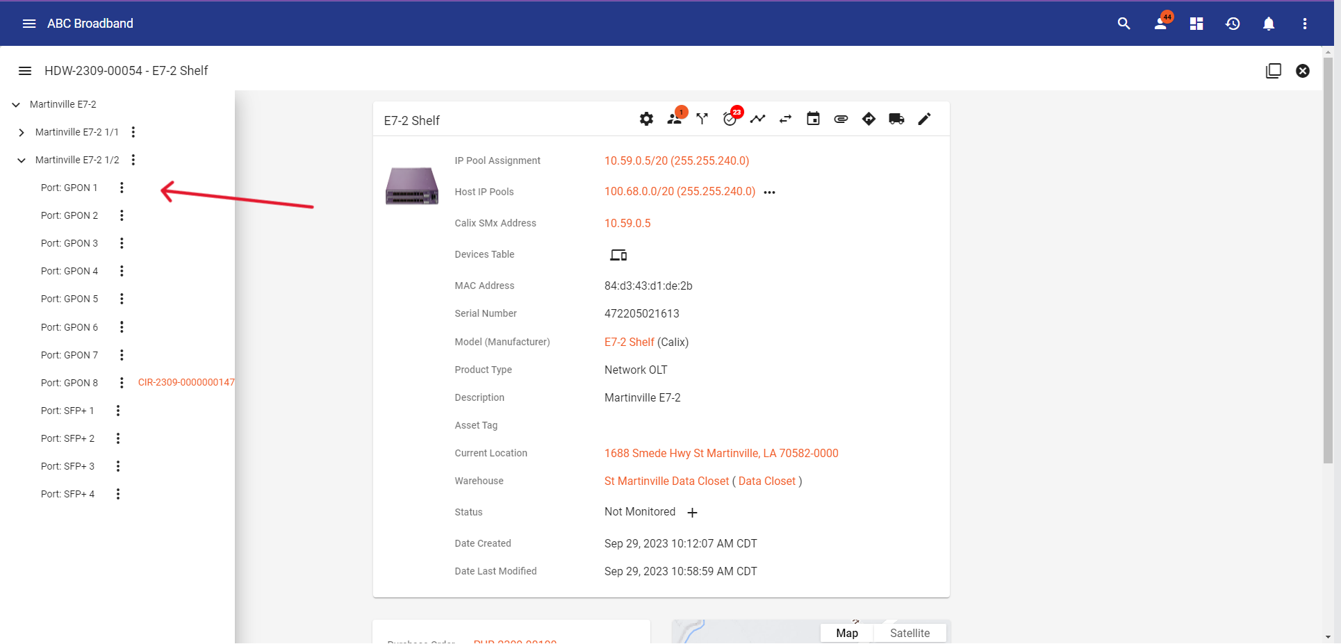
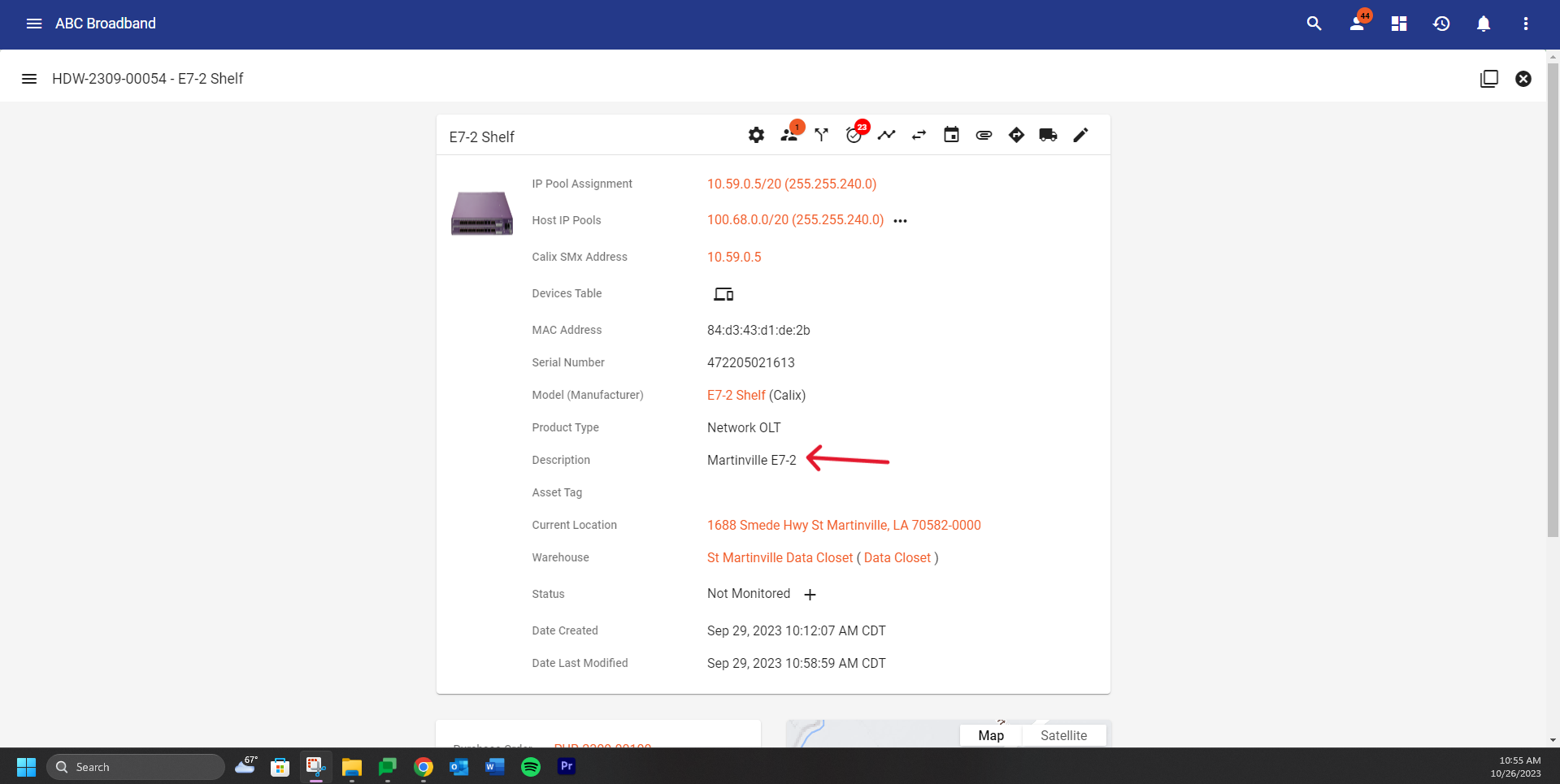
Click into circuit ID to view port from 3GIS drop, next identfiy the E7 shelf you will be using to connect the user.
CIRCUIT ID AND LABEL PORT E7 DEVICE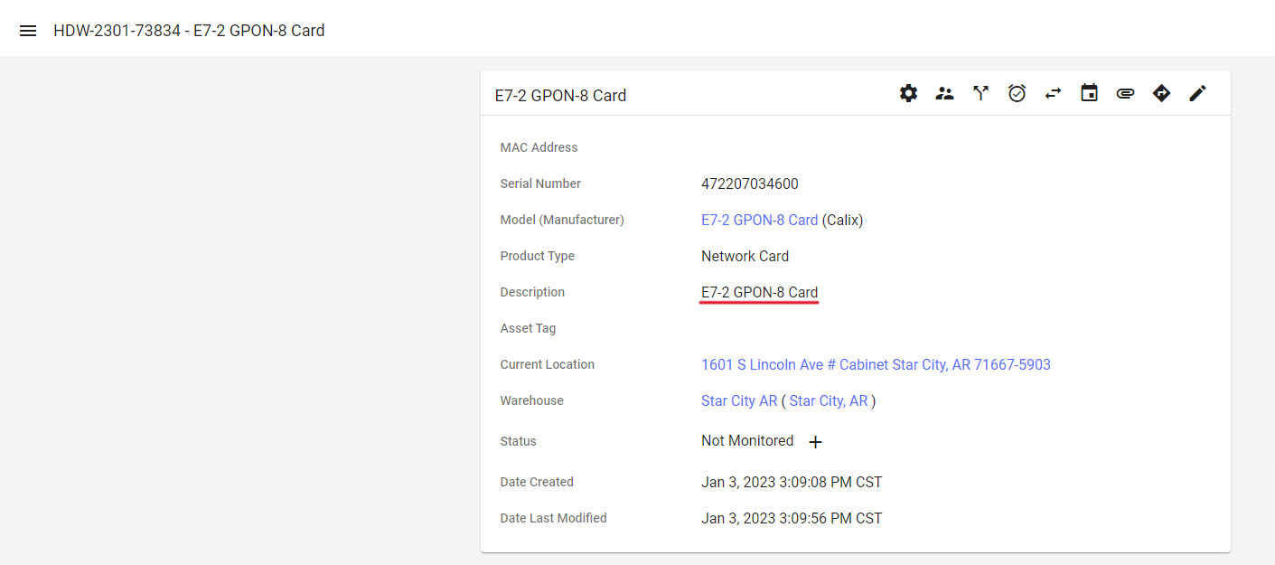
After finding the E7 PON shelf click 
Once finding a E7 shelf you will go to Network 
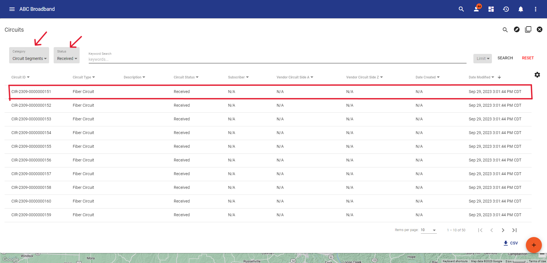
![]() Do an advance search
Do an advance search ![]() for Circuit Segments and Status Received to find a fiber circuit that is being unused
for Circuit Segments and Status Received to find a fiber circuit that is being unused
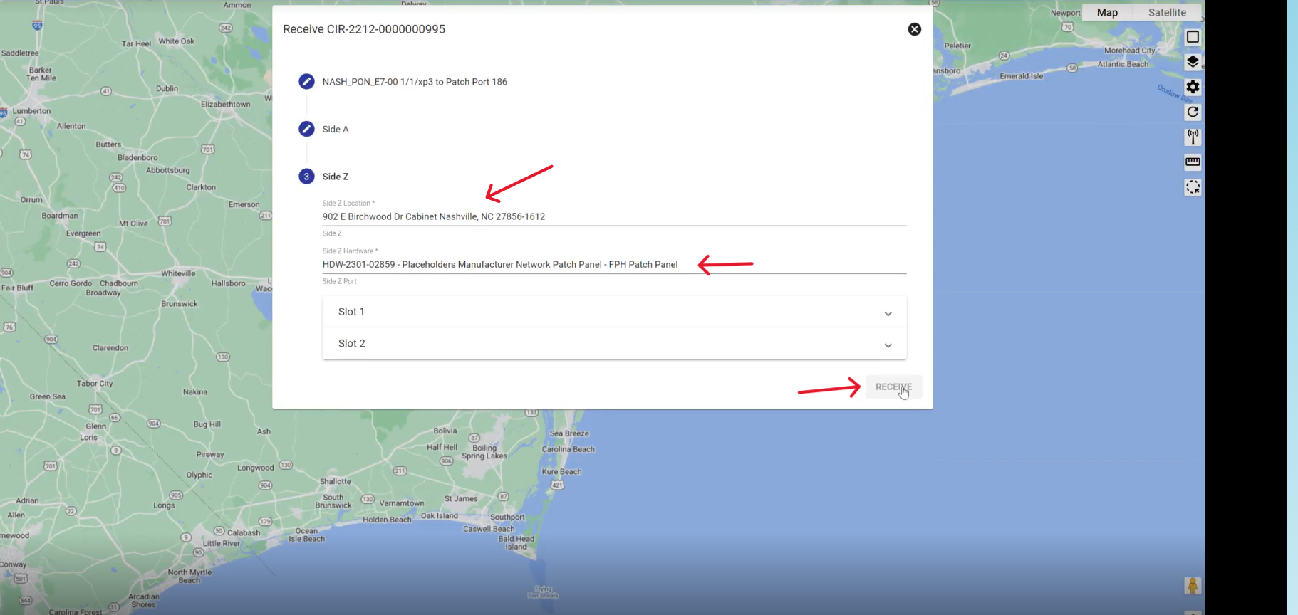
Add a description of the E7 shelf connection that is understandable which you would add to Circuit Segment you found. Where you will connect the E7 to the curcuit to replace the Patch Port
After adding a description you will have to confirm the location and the Hardware ID of the Network card.
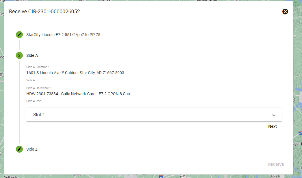
Then confirm the port you plug the hardware into, then it will auto populate the previous address for the cabinet. After, find the Patch port you are importing the new circuit segment for, then click RECEIVE
Go to the parent circuit for the user and change the Side A circuit to the new circuit ID to finish the cross connect
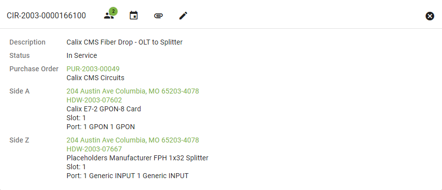
Vendor Circuit
The Vendor Circuit view is similar to a Parent Circuit. In addition to the Description and Status there is a link to the associated Purchase Order. We also see the Side A and Z for this Circuit which shows the location and Hardware (including the slot and port) the Circuit is attached to.
Below the attributes we'll see a list of all the Parent Circuits above this Vendor Circuit.